top of page

Turbomachinery > Clearance Flows
Impact of Large Tip Clearance on Aerodynamic Performance in Turbine
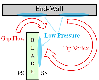
Turbomachines have clearances between the rotor blade tip and casing, and the tip clearance induces unfavorable effect on the system or aerodynamic performance. Small clearances have already been investigated in detail by many. However, large tip clearances have not been investigated even though small turbomachines like turbopumps have relatively large tip clearances due to tolerance limits. Therefore, a detailed investigation of large tip clearance is being conducted.


Tip clearance on turbine blade (left) Schematic of the leakage flow in turbines (right)
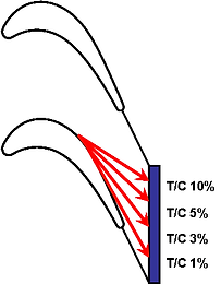
To examine the effect of large tip clearance on aerodynamic performance in a turbine cascade is the main objective of this research. Aerodynamic performance (e.g. loss across rotor row and blade loading) has been measured for tip clearances ranging from 1% to 20% of the blade chord length. CFD simulation has also been conducted and validated with experimental data.


Tip vortex trajectory Streamlines of gap flow
Effects of Seal Cavity Flows on the Aerodynamic Performance in a Shrouded Compressor Stator Passage
In turbomachines, energy is exchanged between rotating components and fluid. In a compressor, rotating blade rows (e.g., rotor) add energy to the fluid by imparting angular momentum, and stationary blade rows (e.g., stator) convert kinetic energy into static pressure of the fluid. Unfortunately, the inevitable gaps between stationary and rotating components lead to leakage flows which cause significant aerodynamic performance degradation.
Shrouding is one way of improving the aerodynamic performance by reducing the leakage flows through the gaps; improving structural integrity; and reducing vibration of blades. When stator blades are shrouded, the hub ends of blades are connected to an annular ring, or the ‘inner-band’, while the upper ends of blades are attached to the casing. Between the inner-band and shrouded cavity endwall, a single or multiple seal-tooth assembly is often used to reduce leakage flow rate through the shrouded cavity.

Schematic of seal-tooth


Experimental result(left) and CFD result(right)
bottom of page
